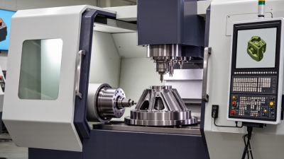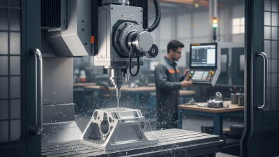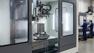
A 5 Axis Cnc Machine can reach several sides of a component in one setup, reducing repositioning and helping preserve feature-to-feature accuracy. But five axes alone do not guarantee faster production or better parts. The right choice depends on the workpiece, tolerances, materials, batch sizes, and the skills available on your shop floor. A tall aluminum housing with angled ports presents different demands from a compact steel impeller.
Market context is useful, but it is not a buying specification. Grand View Research estimated the global CNC machine market at USD 83.99 billion in 2023 and projected a 5.5% compound annual growth rate from 2024 to 2030. That figure covers CNC machines broadly, not five-axis systems alone. Forecasts also depend on each report’s market definitions. Treat them as context, then test your own production assumptions.
Manufacturing researcher Dr. David Dornfeld’s work offers a relevant, non-verbatim takeaway: evaluate a process across the whole production system, not just one machine’s capabilities. In practice, compare spindle performance, rotary-axis design, tool access, control software, probing, service support, and total operating costs. Ask vendors to demonstrate your actual part. Watch the toolpath, inspect the finish, and check setup time. Small details matter. A powerful spindle may still sit idle if programming becomes a bottleneck. This guide examines how to match machine configuration to business needs—and where buyers may need to rethink their expectations.
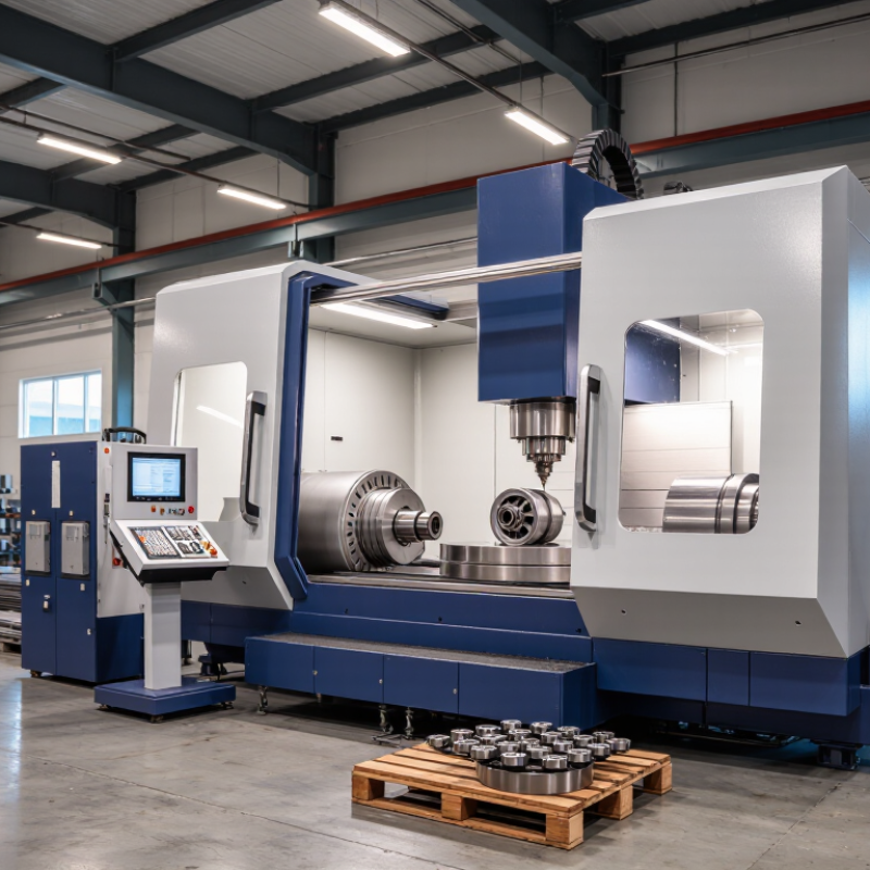
Before comparing machines, map the parts your business actually makes. A five-axis machine has three linear axes—X, Y, and Z—and two rotary axes. The linear axes position the cutting tool across the workpiece. The rotary axes tilt or turn the tool or part, depending on the machine’s design. That movement can reach angled faces and complex contours with fewer repositioning steps.
Look at a representative part, not only your most impressive one. A deep cavity, an angled port, or a curved blade may benefit from five-axis movement. A flat plate with simple holes may not. Not every part needs it. Check the largest workpiece, fixture clearance, tool reach, and required tolerances. Also note how often jobs change and whether parts arrive as one-offs or repeat batches.
Workload shapes the choice. Record materials, typical cutting time, setup time, and weekly production volume. Ask an experienced machinist to review real toolpaths and fixtures; a machine’s advertised axis count cannot confirm that a part will run efficiently. Rotary travel and machine layout matter, too. Two machines with five axes may handle the same part differently. One detail is easy to overlook: extra motion can add programming and setup work. I would verify that against a sample part before committing.
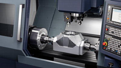
Choosing between 3+2 and simultaneous five-axis machining starts with the part, not the machine brochure. In 3+2 machining, the rotary axes tilt and index the workpiece, then remain fixed while the cutter moves along three linear axes. This approach suits angled holes, milled faces, and parts needing several orientations. Setups can be simpler, and cutting conditions are often easier to predict. But indexed positions may leave awkward tool access on curved surfaces. Small details matter.
Simultaneous machining coordinates all five axes while cutting. It can keep the tool near a useful angle on sculpted forms, deep blends, or turbine-like contours, reducing setups and improving access. That flexibility requires capable CAM software, careful collision checks, and operators who understand rotary limits. Programming time and tool wear can rise when toolpaths are poorly chosen. Less is sometimes enough. A fixture, tool length, or machine stiffness may affect results more than another axis. Compare two real jobs: one with indexed features and one with continuous curves. Record cycle time, finish quality, scrap, and idle time across multiple runs; a single successful demonstration can mislead.
Choose a five-axis machine from real part files, not the largest casting in a brochure. Record each part’s maximum dimensions, fixture height, and tool approach angles. Include the vise, tombstone, probe, and any clearance needed during rotary movement. Measure the awkward part. A 300 mm component may need a much larger working envelope once tilted. Check the manufacturer’s usable travel with the rotary table installed, not just its linear-axis specifications.
Match spindle speed and torque to your materials and cutters. Aluminum parts with small-diameter tools may benefit from high rpm; steel roughing often needs torque at lower speeds. Review the spindle’s torque curve, then compare it with your actual cutting data. Tool capacity matters just as much: list every cutter, probe, and duplicate tool used in a typical job. A 30-tool magazine can become limiting when jobs require long tool lists or unattended cycles.
AMT’s 2023 U.S. Manufacturing Technology Orders report recorded about $4.9 billion in orders, 10.7% below 2022. That investment climate makes fit harder to ignore.
I would still question any choice based only on average parts; one oversized fixture can change the answer. Test representative programs and confirm clearances before buying.
How to Choose a 5 Axis CNC Machine for Your Business?
Before comparing spindle power or table size, ask how the machine’s linear axes are verified. ISO 230-2 describes tests for positioning accuracy and repeatability in numerically controlled axes. These measurements help show whether a commanded movement matches the axis’s actual movement. Small errors can matter when machining a close-fitting pocket or aligning features across several faces.
Request the test conditions and results for each linear axis. Check the measured travel length, positioning deviations, and repeatability in both travel directions. Ask whether the machine was warmed up and whether temperature was recorded. A cold machine in a drafty workshop may behave differently from one running steadily on the shop floor. The details matter.
Look for calibration equipment with traceable measurement records, and confirm that the report identifies the axis and test method clearly. Compare the results with your part tolerances, not just a headline accuracy figure. A clean report is useful. It is not the whole story. I would also ask to see a representative test performed on the machine, though a rushed demonstration can leave questions unanswered. That is worth admitting. Reliable axis data helps you judge whether a five-axis machine can hold position consistently during real production, not merely during a sales presentation.
Sample linear-axis positioning deviations from nominal across five target positions. ISO 230-2 testing evaluates positioning accuracy and repeatability using measurements taken from both approach directions.
Illustrative dataset only—not a certified test report. Values are in micrometres (µm); actual results depend on the machine, axis, test setup, and measurement conditions. When comparing machines, review the ISO 230-2 test report and confirm that accuracy and repeatability meet your part tolerances.
Choosing a five-axis CNC machine means checking more than travel, spindle power, and cycle time. Ask for rotary-axis geometry test results measured using ISO 230-7:2015, which covers geometric accuracy and error motion of rotary axes. Review radial and axial error motion, plus tilt, for both rotary axes. These errors can shift a cutter away from the intended path, especially during simultaneous five-axis moves. Small errors compound.
ISO 230-7 describes test methods; it does not set one universal acceptance limit for every machine. Compare results against your part tolerances and the supplier’s stated test conditions. Check the measurement setup, axis speed, machine temperature, and calibration equipment. Deloitte and MAPI’s 2019 Smart Factory Study reported that 86% of surveyed manufacturers expected smart factory initiatives to drive competitiveness within five years. That finding is not a machine-accuracy benchmark, but it underlines why investment decisions need measurable evidence. A certificate is not the whole story. Review the raw plots, and consider repeating checks after warm-up; this practical detail is easy to overlook.
Tips: Ask for raw plots, not just pass/fail results. Confirm the axis positions and test conditions, then compare them with your tightest real part tolerance.
| Machine Configuration | Rotary-Axis Geometry | Relevant ISO 230-7 Checks | What to Request from the Supplier | Best Fit and Selection Consideration |
|---|---|---|---|---|
| Trunnion table | The workpiece is carried by a tilting axis and a rotary axis. The workpiece’s position and leverage change as the table tilts. | Radial, axial, and tilt error motion for each applicable axis of rotation; synchronous and asynchronous components where reported. | Test setup and instrument details; results for each rotary axis; stated measurement conditions; and the supplier’s proposed acceptance limits. | Often suited to compact parts and multi-side machining. Check table load, workpiece clearance, and how the part’s weight affects rotary-axis performance. |
| Swivel-head configuration | One or more rotary axes are located in the spindle head, changing tool orientation without tilting the workpiece table. | Radial, axial, and tilt error motion of each tested rotary axis. Confirm which axis positions and test orientations are included in the report. | Separate results for each rotary axis, with the measurement arrangement and any limitations caused by head position or spindle configuration. | Useful for large or heavy workpieces. Evaluate head reach, tool access, collision envelope, and how rotary-axis errors affect tool-tip position. |
| Head-and-table configuration | Rotary axes are split between the spindle head and the workholding table, so both tool and workpiece orientation contribute to the setup. | ISO 230-7 error-motion results for each applicable axis of rotation, assessed separately rather than as a single combined figure. | Axis-by-axis test records and an explanation of how the machine’s volumetric or tool-centre-point performance is verified in addition to rotary-axis tests. | Can provide flexibility across part sizes. Consider axis coordination, calibration requirements, workholding, and the combined effect of multiple axes. |
| Rotary table on a 3-axis machine | A rotary table adds a workpiece rotation axis; a separate tilting axis may be present in some configurations. | Radial, axial, and tilt error motion for each rotary axis covered by the test plan. | Results for the table in the installed configuration, plus details of payload, fixture, and measurement conditions used during testing. | May suit lower-cost upgrades or defined part families. Verify axis range, payload, integration, and whether the added axis meets the required access and accuracy needs. |
| Universal or articulating rotary head | Multiple head rotations provide a wide range of tool orientations; axis arrangement and working range vary by machine design. | ISO 230-7 checks for each applicable rotational axis, with results clearly linked to the tested axis and configuration. | Axis-specific reports, stated test positions, and a description of how the manufacturer verifies performance across the working envelope. | Useful where tool orientation and access are priorities. Compare head stiffness, reach, collision limits, and verification coverage across relevant positions. |
| Any 5-axis configuration: acceptance review | Rotary-axis geometry is one part of machine performance; it does not by itself describe full machine volumetric accuracy or machining results. | Review radial, axial, and tilt error motion, including synchronous and asynchronous components when applicable to the test report. | Agree in writing on acceptance limits, test conditions, measurement uncertainty, axis positions, and any additional tests needed for the intended application. | ISO 230-7 specifies test methods for geometric accuracy of axes of rotation; it does not set one universal pass/fail tolerance for every machine or application. |
| Selection note: Compare like-for-like test conditions and axis configurations. Use the ISO 230-7 report to assess rotary-axis error motion, then evaluate work envelope, payload, thermal behavior, control capability, and application-specific machining requirements separately. | ||||